
1-805-484-2992
Quotes - Engineering - SalesU-Tube Heat Exchanger Construction
One Tubesheet, Free Expansion, Removable Bundle
In a U-tube bundle every tube is bent through 180 degrees so both ends terminate in a single tubesheet. One fluid enters the bonnet, travels down one leg of every tube, turns through the bend and returns through the other. The second fluid flows around the outside of the bundle in the shell.
Free thermal expansion is the defining property. Each tube is anchored at the tubesheet and free at the bend, so it grows and contracts without transmitting load into the shell or the tubesheet. Tubes can even sit at different temperatures from one another without consequence. That removes the expansion joint a fixed tubesheet unit needs, along with the most common leak path on cycling duty.
The bundle comes out. With one tubesheet and no rear head to unbolt, the bundle withdraws from the shell as a single assembly. The shell interior and the outside of every tube can then be inspected, brushed or hydroblasted. On any duty where the fouling fluid is on the shell side, that is the difference between an exchanger you can maintain and one you can only flush.
The trade-off is real. A brush or lance will not negotiate a 180 degree bend, so tube-side mechanical cleaning is effectively unavailable. Put the clean fluid in the tubes. And because fluid enters one leg and leaves the other, the pass count is always even, which is why catalogued arrangements run 2, 4 and 6 pass rather than odd numbers.
Where it appears in the range. The SU, WU, OC, HTWU and the tank heater bundles are all U-tube construction, as are the compact CHX and CHXS. The double-wall ranges use the same geometry with double-wall tubes.
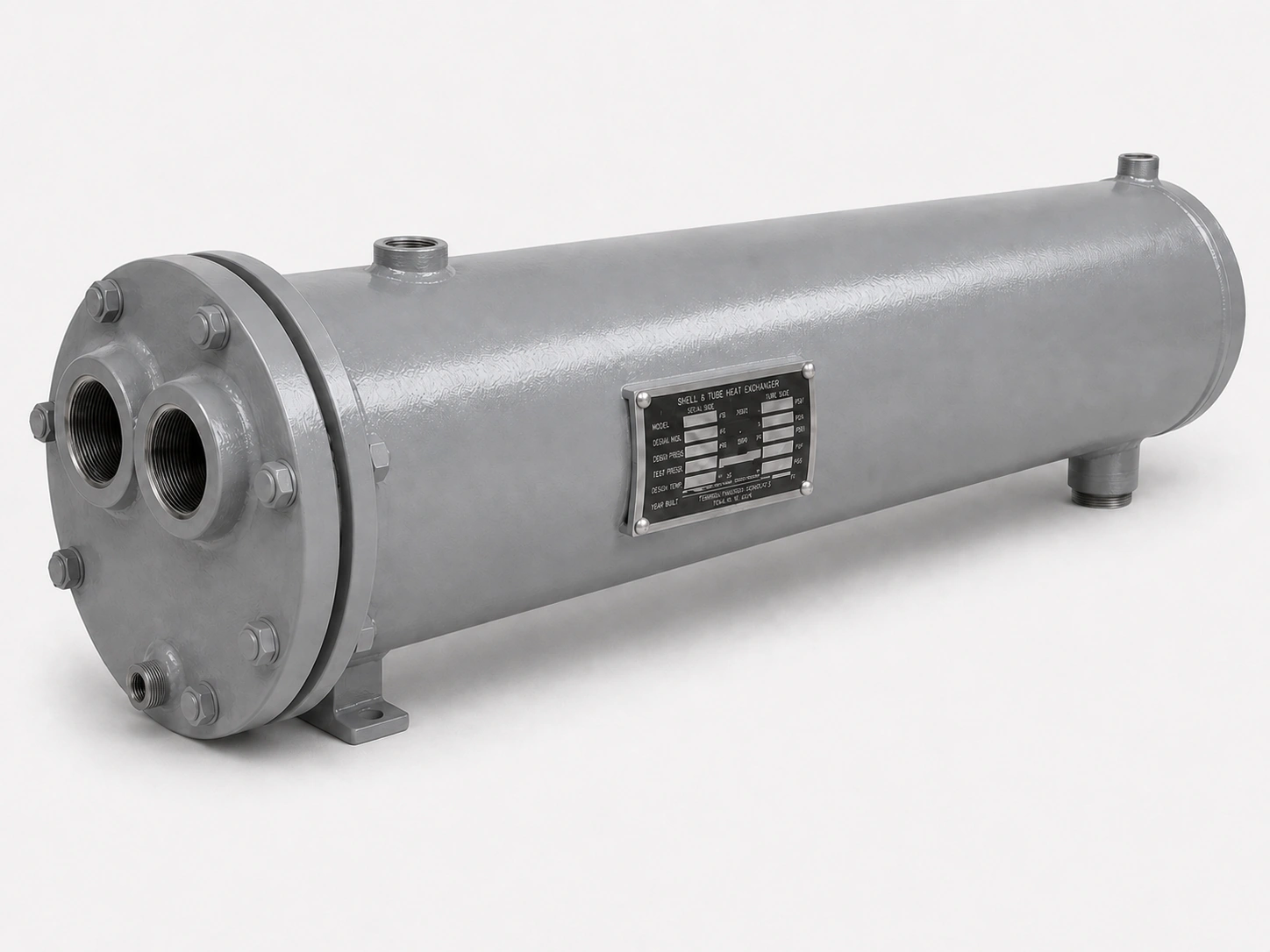
U-Tube Configuration
Shell diameter, shell length and pass count are set by the duty and recorded in the catalogued part number.
Configuration
- Tubesheets: One
- Tube arrangement: U-bend, 180 degrees
- Bundle: Removable
- Expansion: Free, no joint required
Features
- Full shell-side access
- No expansion joint
- Tolerates thermal cycling
- Even pass counts only
- Bundle replaceable
Typical Series
- SU steam-to-liquid
- WU liquid-to-liquid
- OC oil cooler
- HTWU high tube pressure
- TCS and TCW tank heaters
| CONSTRUCTION | TUBESHEETS | EXPANSION | BUNDLE |
| U-Tube | One | Free | Removable |
Working With U-Tube Units
Put the Clean Fluid in the Tubes
This is the practical rule that follows from the geometry, and it is the reverse of the usual advice for straight-tube exchangers. On a U-tube unit the cleanable side is the shell side, so treated water, clean steam and closed-loop glycol belong in the tubes and the fouling process stream belongs in the shell.
Getting this backwards produces a unit that cannot be maintained. It is worth checking on an existing installation, because a change of duty over the years occasionally leaves the fouling fluid on the wrong side.
Plugged Tubes and Bundle Replacement
A failed tube on a U-tube bundle is plugged at both legs on the tubesheet face. That takes the tube out of service and removes its surface area, and the flow distribution shifts slightly across the remaining tubes.
Individual tube replacement is not practical the way it is on a straight-tube bundle. Track the plugged tube count as a maintenance indicator, and once it reaches the low single-digit percentages it is worth costing a replacement bundle against continued plugging.
Common FAQs
Because the fluid physically enters one leg of the U and returns through the other, which is two passes by definition. Four and six pass arrangements add partition plates in the bonnet, but the count stays even. Catalogued Bell & Gossett arrangements are 2, 4 and 6 pass for this reason.
Chemically yes, mechanically only partly. Nothing rigid passes a 180 degree bend, so brushing or rodding end to end is not available. High-pressure water reaches into the straight sections. This is why the clean fluid belongs in the tubes.
At least the bundle length in line with the shell, plus room to handle and set it down. It is the most commonly forgotten layout item and expensive to fix once the unit is piped in.
Slightly. The innermost tubes cannot be bent to zero radius, so a minimum bend radius leaves an untubed lane down the centre of the bundle. For a given shell diameter that means marginally less surface than a straight-tube bundle.
Most of the range: SU, WU, OC, HTWU, CHX, CHXS and the TCS and TCW tank heaters. The DSU, DWU, DTCS and DTCW use the same geometry with double-wall tubes.
Related

U-TUBE • DOUBLE WALL
Double-Wall U-Tube
A vented gap between two tube walls, for potable water duty.
+ Learn More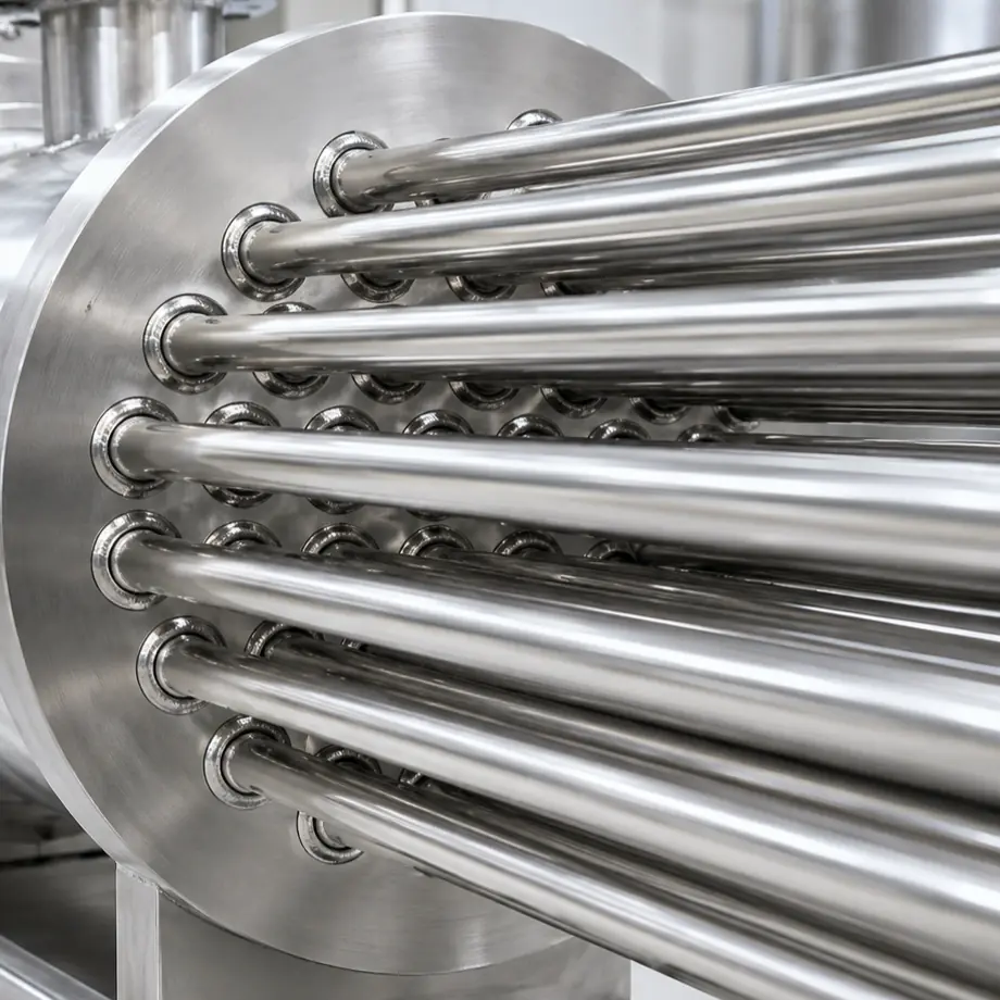
HEAVY DUTY • 400 PSI
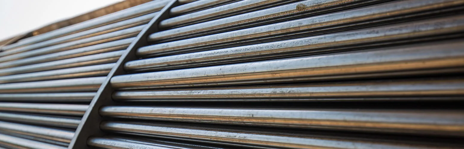
Heavy-Duty U-Tube
The same geometry rated for 400 PSI on the tube side.
+ Learn More